Installation and configuration of DNS Server:
 |
| Client server DNS |
those that can be directly used by the user, such as e-mail, and those that support other application programs.The Domain Name System (DNS) is a supporting program that is used by other programs such as e-mail.
an example of how a
DNS client/server program can support an
e-mail
program to find the IP address of an e-mail recipient. A user of an e-mail
program
may
know the e-mail address of the recipient; however, the IP protocol needs the
IP
address. The DNS client program sends a request to a DNS server to map the
e-mail
address
to the corresponding IP address.
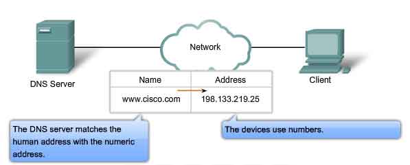
To identify an entity, TCPIIP
protocols use the IP address, which uniquely identifies
the connection of a host to the
Internet. However, people prefer to use names
instead of numeric addresses.
Therefore, we need a system that can map a name to an
address or an address to a name.
NAME SPACE
To be unambiguous, the names
assigned to machines must be carefully selected from a
name space with complete control
over the binding between the names and IP addresses.
In other words, the names must be
unique because the addresses are unique. A name
space that maps each
address to a unique name can be organized in two ways: fiat or
hierarchical.
Flat Name Space
In a flat name space,
a
name is assigned to an address. A name in this space is a
sequence of characters without structure.
In a hierarchical
name space, each
name is made of several parts. The first part can
define the nature of the
organization, the second part can define the name of an organization,
the third part can define departments in the
organization, and so on.
DOMAIN NAME SPACE
To have a hierarchical name
space, a domain
name space was
designed. In this design
the names are defined in an
inverted-tree structure with the root at the top. The tree can
have only 128 levels: level 0 (root) to level 127
(see Figure 2).
Figure
2 Domain name space

Figure
3 Domain names and labels

A
domain is a subtree of the domain name space. The name of the domain is
the domain
name of
the node at the top of the subtree. Figure 25.5 shows some domains. Note that a
domain may itselfbe
divided into domains (or subdomains as they are sometimes called).
Figure 5 Domains


Zone
Since the complete domain name hierarchy cannot be stored on a single server, it is
called a zone. We can define a zone as a contiguous
part of the entire tree.
A
server can also divide part of its domain and delegate responsibility but still
keep
part of the domain for itself. In
this case, its zone is made of detailed information for the
Figure 7 Zones and domains

Root Server
A root server is a server
whose zone consists of the whole tree. A root server usually
does not store any information
about domains but delegates its authority to other servers,
keeping references to those
servers. There are several root servers, each covering the
whole domain name space. The
servers are distributed all around the world.
Primary
and Secondary Servers
DNS defines two types of servers: primary and secondary. A primary server is a server
that stores a file about the zone
for which it is an authority. It is
responsible for creating,
maintaining, and updating the
zone file. It
stores
the zone file on a local disk.
A secondary
server is
a server that transfers the complete information about a
zone from another server (primary
or secondary) and stores the file on its local disk. The
secondary server neither creates
nor updates the zone files. If updating
is required, it must be done by the primary server, which sends the
updated version to the secondary
Socket Programing
Socket Programing